|
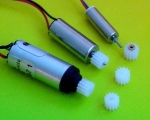
Les us consider a first frequent case, with a 12 teeth POM pinion
to be inserted on the axis of a 6mm pager motor. The motor axis
is 0.80 mm, the pinion 0.78 mm, so it is a perfect match, that will
not stress the gear, and allow for a rather easy insertion and possible
removal, but an adequate tool is required.
The 12 teeth pinions are not symetrical. It is important to look
carefully, using a watchmaker lens, at the gear and notice the hole
is slightly smaller at one end, and the gear side is slighthy rounded;
this will facilitate the insertion of our propeller connectors.
It facilitates also the insertion on the shaft, and the additional
force due to the smaller extremitiy diameter increases the retention
force when fully inserted. But now, be carefull; If you push the
gear on the motor, the shaft may be pushed inside the motor, so
for the collector that will deform the brushes.
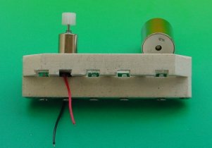
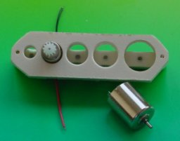
You need an adequate tool for maintaining the axis. The motor is
placed in a hole with a thin screw (less than 1.6mm) pushing on
the axes, that is on the collector around the axes. Round the extremity
of the screw, in order to have a regular effort. Now you can depress
your gear.
Removing the gear must be done by inserting a thin V-shaped sheet
of metal between the gear and the motor, and using a 0.7mm needle
to press on the axis, the gear being maintaind by the sheet metal.
|
 |